Pioneer 300-S - Manuels
Pioneer 300-S - Notice en ligne au format PDF.
Manuels:
Notice Pioneer 300-S


Résumé
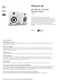
4 <DRB1206>En/Fr CONTENTS CAUTIONS REGARDING HANDLING .................. 4CHECKING ACCESSORIES ................................... 5 FEATURES .............................................................. 5 CONNECTIONS ...................................................... 6 1. Connection of I...
5 <DRB1206> En/Fr CHECKING ACCESSORIES CONTROLE DES ACCESSOIRES • Operating instructions • Mode d'emploi FEATURES CARACTERISTIQUES PRINCI-PALES Compteur BPM Le compteur auto BPM incorporé permet de vérifier visuel-lement le tempo de la musique. Ce compteur peut afficherdes valeurs en temps rée...
6 <DRB1206>En/Fr CONNECTIONS Before making or changing the connections, switch off thepower switch and disconnect the power cord from the ACoutlet. CONNEXION Avant d'effectuer les raccordement, ou de les modifier,veillez à couper l'alimentation et à débrancher la fiche ducordon d'alimentation....
Pioneer Manuels
-
 Pioneer DMH W3050NEX
Manuel d'utilisation
Pioneer DMH W3050NEX
Manuel d'utilisation
-
 Pioneer TS A653CH
Manuel d'utilisation
Pioneer TS A653CH
Manuel d'utilisation
-
 Pioneer DM 40
Guide de dépannage
Pioneer DM 40
Guide de dépannage
-
 Pioneer DMH W4600NEX
Manuel d'utilisation
Pioneer DMH W4600NEX
Manuel d'utilisation
-
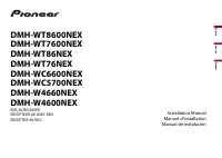
Pioneer DMH WT76NEX
Manuel d'utilisation
-
 Pioneer DMHWC5700NEX
Manuel d'utilisation
Pioneer DMHWC5700NEX
Manuel d'utilisation
-
 Pioneer CD IU52
Manuel d'utilisation
Pioneer CD IU52
Manuel d'utilisation
-
 Pioneer VREC
Manuel d'utilisation
Pioneer VREC
Manuel d'utilisation
-
 Pioneer DDJ 200
Guide de dépannage
Pioneer DDJ 200
Guide de dépannage
-
Pioneer DMH WT7600NEX
Manuel d'utilisation
-
 Pioneer DEH S4220BT
Manuel d'utilisation
Pioneer DEH S4220BT
Manuel d'utilisation
-
 Pioneer AVH 120BT
Manuel d'utilisation
Pioneer AVH 120BT
Manuel d'utilisation
-
 Pioneer VREC DH200
Manuel d'utilisation
Pioneer VREC DH200
Manuel d'utilisation
-
 Pioneer AVH 1550NEX
Manuel d'utilisation
Pioneer AVH 1550NEX
Manuel d'utilisation
-
 Pioneer K110
Manuel d'utilisation
Pioneer K110
Manuel d'utilisation
-
Pioneer ND BC8
Manuel d'utilisation
-
Pioneer CDIU52
Manuel d'utilisation
-
 Pioneer AVH 271BT
Manuel d'utilisation
Pioneer AVH 271BT
Manuel d'utilisation
-
 Pioneer CDVM1
Manuel d'utilisation
Pioneer CDVM1
Manuel d'utilisation
-
 Pioneer K012
Manuel d'utilisation
Pioneer K012
Manuel d'utilisation